How to configure VFD

Some devices that CoreELEC supports have a VFD similar to the TX3 Mini as shown below.

tx3

Many of these are supported in our builds thanks to @TheCoolest.

To get these working is really easy.

  1. Goto Arthur’s VFD repository here.
  2. Download the configuration that matches your device and rename it to vfd.conf.
    Make sure that you save the file as Raw.
  3. Copy the vfd.conf to /storage/.config on your device.
  4. Install OpenVFD Service via the CoreELEC repository in Kodi.
  5. Reboot and enjoy.

There is only 1 device at present, that requires the use of a custom DTB which is the A95X-R2 and this can be found in the device_trees folder on your sd-card/usb drive.

4 Likes

A MILLION thanks for this information. I never thought I would get my front clock working without the original firmware. I have the M82. Any way to get the display to show a 12-hour versus 24-hour clock? Settings inside CoreElec are set and display time in 12-hour format. Thank you.

There is no support for 12H/24H selection at this point.

1 Like

Then 24 hour clock it is. I am VERY happy to have my clock back! Thank you sooo much for the hard work you did to put all of this information together. Much appreciated.

Is there a wy to show local time instead of UTC?

UTC? It uses the system time. If your box doesn’t have the correct time, it won’t show correctly on the VFD.

Hm. Kodi shows correct time. Looks like kodi’s timezone is independent of system’s. I’ll check it

I had different timezone in kodi & system. I had no /storage/.cache/timezone file.
So I just did echo "TIMEZONE=Europe/Moscow" >> /storage/.cache/timezone and everything became OK after reboot.

Hello,

I have a Alfawise S95 box, and I installed Coreelec 8.90.4 .
I have tried all the dtb’s in the memory card, but the box is allways displaying “boot”.

I installed openvfd and tried several vfd.conf files, but the display never changes,

Is there anything that I’m not doing right?

Regards.

  1. You only need the regular DTB from CoreELEC SD card for your SoC, don’t use any other DTBs.
  2. If you tried a few vfd.conf files and it still isn’t working, I’ll need the DTB from the Android installation.
  3. I’ll need to know what icons the box has. (top - right to bottom - left)

Edit: I just found a disassembled image of the box, it looks like a rebadged TX3 Mini. Try the vfd.conf for the tx3 and see if it works.
http://freaktab.com/forum/tv-player-support/amlogic-based-tv-players/s905x/683266-alfawise-s95-amlogic-s905w-android-7-1-2-16gb-rom-2-4ghz-wifi-4k-100mbps-lan?p=683269#post683269 - scroll down.

First, Thank You! I was tired o the Word “Boot” on the display.
Second, If anyone owns a Alfawise S95, just use the TX3 Mini dtb.img and vfd.conf, it’ll work perfectly.

1 Like

Great information. Thank you!!!

Just purchased a TicTid X9T Pro (S912, 3Gb, 1Gb NIC) and it has been working well with CoreElec.

I am so impressed with this little box turning another one in to an automation server (HA / MQTT / Node Red)

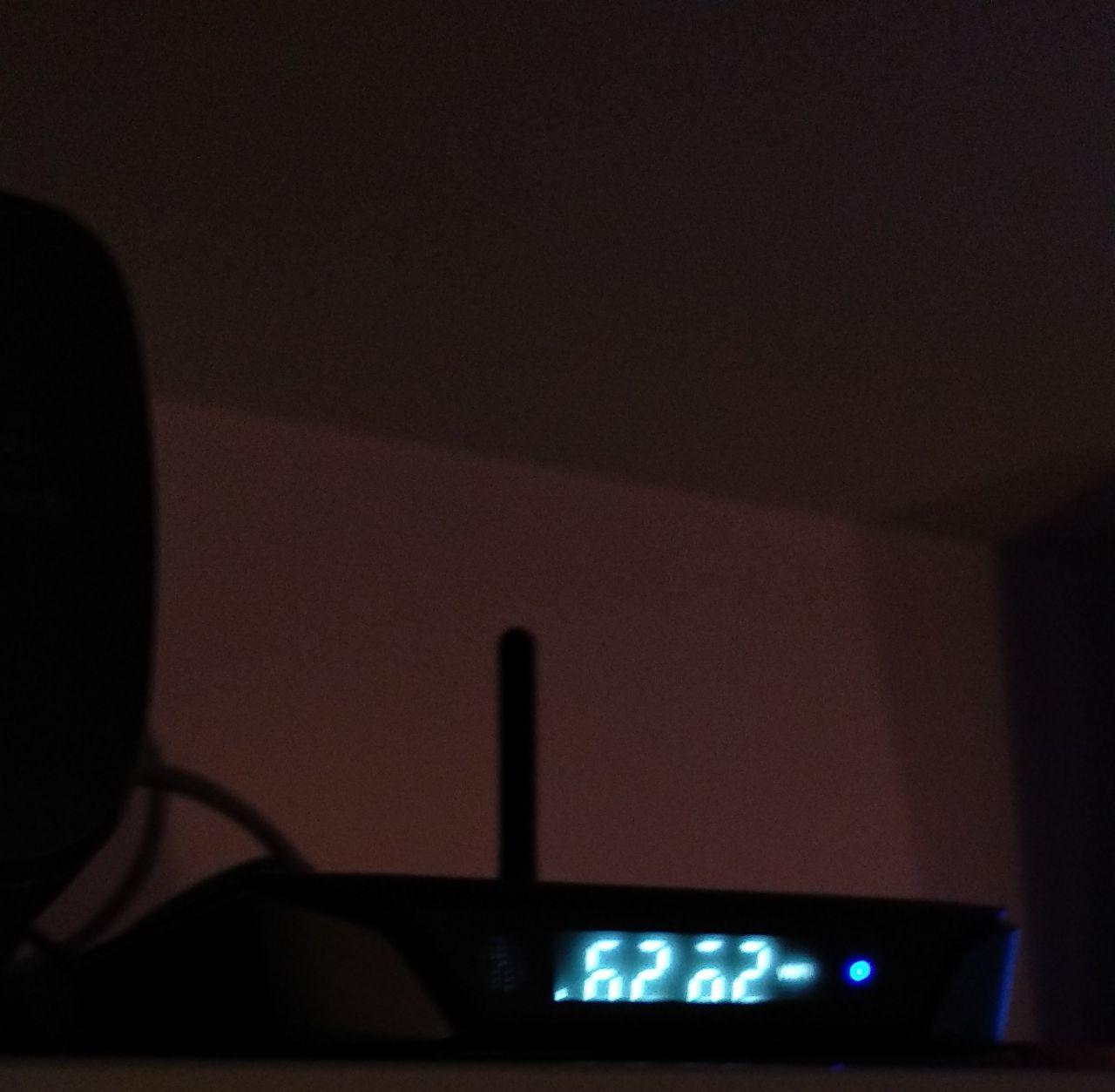
Tried using tanix-tx9-pro-vfd.conf for clock display and it shows a couple of alpha numeric characters and zeros. Tried a couple of others with the same results.

Info:
CoreELEC (official): 9.0.1 (Amlogic.arm)
uname -a
Linux ICS-X9T 3.14.29 #1 SMP Wed Feb 27 00:10:49 GMT 2019 aarch64 GNU/Linux

Using DTB:
gxm_q201_3g_1gbit.dtb

Clock display and configuration:

clock

VFD file configuration:
# This file must be renamed to vfd.conf and placed in the /storage/.config/ folder.
#
# Tanix TX9 Pro configuration
#--------------------
#gpio_xxx:
# [0] 0 = &gpio, 1 = &gpio_ao.
# [1] pin number - hxxps://github.com/openSUSE/kernel/blob/master/include/dt-bindings/gpio/meson-gxl-gpio.h
# [0] Reserved - must be 0.

dmesg shows:
[ 16.288198@0] OpenVFD: Version: V1.3.0
[ 16.288216@0] OpenVFD: vfd_gpio_clk: #0 = 0x00; #1 = 0x4C; #2 = 0x00;
[ 16.288222@0] OpenVFD: vfd_gpio_dat: #0 = 0x00; #1 = 0x4B; #2 = 0x00;
[ 16.288243@0] OpenVFD: vfd_gpio_stb: #0 = 0x00; #1 = 0x35; #2 = 0x00;
[ 16.288246@0] OpenVFD: vfd_gpio0: #0 = 0x00; #1 = 0x00; #2 = 0xFF;
[ 16.288249@0] OpenVFD: vfd_gpio1: #0 = 0x00; #1 = 0x00; #2 = 0xFF;
[ 16.288252@0] OpenVFD: vfd_gpio2: #0 = 0x00; #1 = 0x00; #2 = 0xFF;
[ 16.288255@0] OpenVFD: vfd_gpio3: #0 = 0x00; #1 = 0x00; #2 = 0xFF;
[ 16.288260@0] OpenVFD: vfd_chars: #0 = 0x04; #1 = 0x00; #2 = 0x01; #3 = 0x02; #4 = 0x03;
[ 16.288266@0] OpenVFD: vfd_dot_bits: #0 = 0x00; #1 = 0x01; #2 = 0x02; #3 = 0x03; #4 = 0x04; #5 = 0x05; #6 = 0x06;
[ 16.288269@0] OpenVFD: vfd_display_type: #0 = 0x00; #1 = 0x00; #2 = 0x00; #3 = 0x00;
[ 16.288275@0] OpenVFD: Detected gpio chips: ao-bank, banks.
[ 16.288281@0] OpenVFD: “banks” chip found. base = 155, pin count = 101, pin = 76, offset = 231
[ 16.288283@0] OpenVFD: “banks” chip found. base = 155, pin count = 101, pin = 75, offset = 230
[ 16.288285@0] OpenVFD: “banks” chip found. base = 155, pin count = 101, pin = 53, offset = 208
[ 16.288287@0] OpenVFD: Skipping vfd_gpio0 evaluation (0xFF)
[ 16.288289@0] OpenVFD: Skipping vfd_gpio1 evaluation (0xFF)
[ 16.288292@0] OpenVFD: Skipping vfd_gpio2 evaluation (0xFF)
[ 16.288302@0] OpenVFD: Skipping vfd_gpio3 evaluation (0xFF)
[ 16.307476@6] OpenVFD: Select FD628 controller
[ 16.307525@6] OpenVFD: SPI 3-wire interface intialized (LSB mode)

Any suggestions?

Hi, is there vfd.conf for the t10 max? Here I leave the dtb, in case it helps. @TheCoolest

https://www11.zippyshare.com/v/nct1gctX/file.html

Try this vfd.conf and let me know if it works or not.
t10max-vfd.conf (1.2 KB)

@pete
Sorry for the late reply, please try this config and see if it looks any better.
x9t-pro-vfd.conf (1.2 KB)

It shows like this. I’m sorry for the quality.

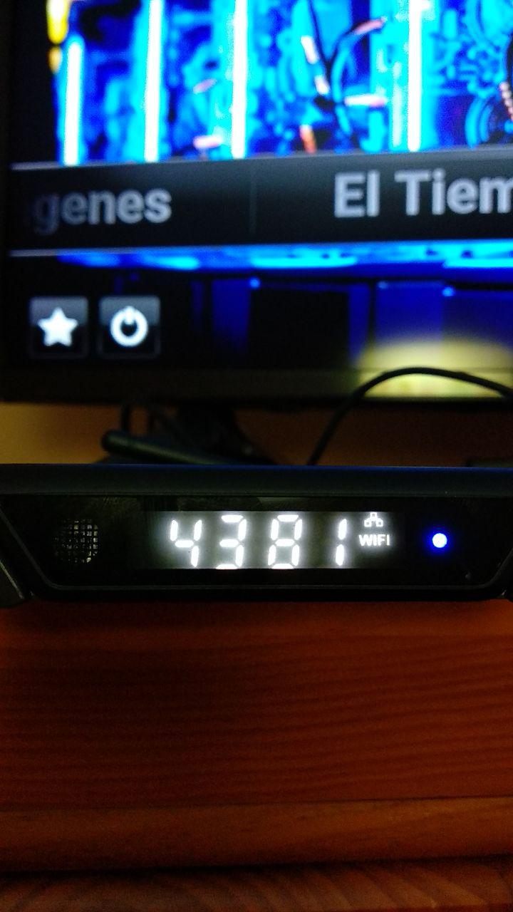
Try changing the last line in the file from
vfd_display_type='0x00,0x00,0x00,0x01'
to
vfd_display_type='0x01,0x00,0x00,0x01'
or
vfd_display_type='0x07,0x00,0x00,0x01'
Reboot after change to see the effect.

With the “vfd_display_type=‘0x07,0x00,0x00,0x01’`”

It shows like this.

P.D: It’s 18:34 when the photo was taken. @TheCoolest

Then change the order of the chars:
vfd_chars=‘4,0,1,2,3’ to vfd_chars=‘4,3,2,1,0’

vfd_chars=‘4,3,2,1,0’ ok. al is worKing
good. only colon dont shows .

For the colon, and other symbols, you have to find out on your own by modifying vfd_dot_bits order, e.g.
vfd_dot_bits=‘0,1,2,3,4,5,6’, and then moving the 4 (=COL) to other position

1 Like