I have managed to dump the android DTB file (Using fdtdump), and found the following entry, which looks like it is for the display controller:
fd628_dev {
    compatible = "amlogic, fd628_dev";
    status = "okay";
    clk_pin = <0x00000028 0x0000000c 0x00000000>;
    dat_pin = <0x00000028 0x0000000c 0x00000000>;
    stb_pin = <0x00000028 0x00000002 0x6d706174>;
};
But I don’t understand why the CLK and DAT pin are the same?
CLK = DAT = Pin 12?, STB = Pin 2? On the Banks GPIO? (phandle 0x28)
There is also an entry for something called the pinmux with seems to list the two GPIO banks discussed in the OpenVFD doco.
pinmux {
    compatible = "amlogic, pinmux-gxl";
    dev_name = "pinmux";
    #pinmux-cells = <0x00000002>;
    #address-cells = <0x00000002>;
    #size-cells = <0x00000002>;
    reg = <0x00000000 0x00000003 0x62616e6b 0x00000003>;
    ranges;
    banks@c11080b0 {
        reg = <0x00000000 0x00000000 0x00000000 0x00000000 0x00000003 0x70756c6c 0x00677069 0x00000494 0x00000002 0x00000028 0x00000028 0x616e6b40 0x00000003 0xc8100014 0xc810002c 0xc8100024>;
        reg-names = "mux", "pull", "pull-enable", "gpio";
        gpio-controller;
        #gpio-cells = <0x00000002>;
        linux,phandle = <0x00000028>;
        phandle = <0x00000028>;
    };
    ao-bank@c1108030 {
        reg = <0x00000000 0x00000000 0x00000000 0x00000003 0x70756c6c 0x00000000 0x000004a4 0x000000df 0x000000e5 0x65787465 0x73000000 0x00000004>;
        reg-names = "mux", "pull", "gpio";
        gpio-controller;
        #gpio-cells = <0x00000002>;
        linux,phandle = <0x0000006f>;
        phandle = <0x0000006f>;
    };
If I also dump the dtb file from coreElec I do notice slight differences? See (linux,phandle)
pinmux {
compatible = “amlogic, pinmux-gxl”;
dev_name = “pinmux”;
#pinmux-cells = <0x00000002>;
#address-cells = <0x00000002>;
#size-cells = <0x00000002>;
reg = <0x00000000 0x00000003 0x62616e6b 0x00000003>;
ranges;
banks@c11080b0 {
reg = <0x00000000 0x00000000 0x00000000 0x00000000 0x00000003 0x70756c6c 0x00677069 0x000004a4 0x00000002 0x0000001a 0x0000001a 0x616e6b40 0x00000003 0xc8100014 0xc810002c 0xc8100024>;
reg-names = “mux”, “pull”, “pull-enable”, “gpio”;
gpio-controller;
#gpio-cells = <0x00000002>;
linux,phandle = <0x0000001a>;
phandle = <0x0000001a>;
};
ao-bank@c1108030 {
reg = <0x00000000 0x00000000 0x00000000 0x00000003 0x70756c6c 0x00000000 0x000004b4 0x000000ef 0x000000f5 0x65787465 0x73000000 0x00000004>;
reg-names = “mux”, “pull”, “gpio”;
gpio-controller;
#gpio-cells = <0x00000002>;
linux,phandle = <0x0000006d>;
phandle = <0x0000006d>;
};
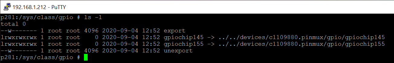
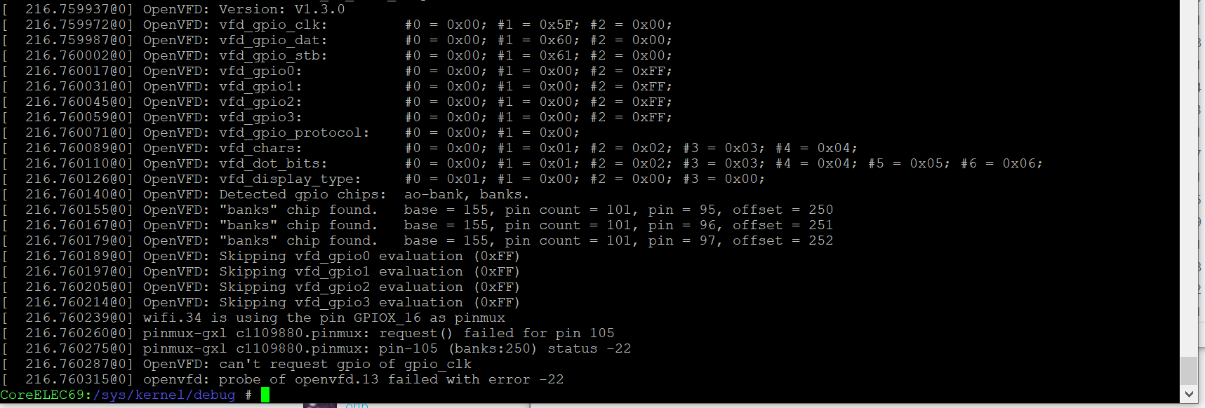
Also I notice in the system log, OpenVFD says it found the GPIO chips. ao-bank, banks. Since the configuration I’m using is trying to address the banks chip, What does the Base 155 mean? Does this map to any of the address information in the DTB file?
 I’m using CoreELEC-Amlogic.arm-9.2.4.1-Generic.img.gz on an SD card with …/device_trees/gxl_p212_2g.dtb as my dtb.img