Is there a way you could share your working program?
Hello,
I have this box. https://www.aliexpress.com/item/1005001335327312.html
dmesg:
CoreELEC:~ # dmesg | grep Open
[ 0.389633@1] ohci_hcd: USB 1.1 ‘Open’ Host Controller (OHCI) Driver
[ 21.261363@3] OpenVFD: Version: V1.3.0
[ 21.261384@3] OpenVFD: vfd_gpio_clk: #0 = 0x00; #1 = 0x41; #2 = 0x00;
[ 21.261390@3] OpenVFD: vfd_gpio_dat: #0 = 0x00; #1 = 0x40; #2 = 0x00;
[ 21.261395@3] OpenVFD: vfd_gpio_stb: #0 = 0x00; #1 = 0x00; #2 = 0xFF;
[ 21.261401@3] OpenVFD: vfd_gpio0: #0 = 0x00; #1 = 0x00; #2 = 0xFF;
[ 21.261406@3] OpenVFD: vfd_gpio1: #0 = 0x00; #1 = 0x00; #2 = 0xFF;
[ 21.261411@3] OpenVFD: vfd_gpio2: #0 = 0x00; #1 = 0x00; #2 = 0xFF;
[ 21.261416@3] OpenVFD: vfd_gpio3: #0 = 0x00; #1 = 0x00; #2 = 0xFF;
[ 21.261513@3] OpenVFD: vfd_gpio_protocol: #0 = 0x00; #1 = 0x00;
[ 21.261521@3] OpenVFD: vfd_chars: #0 = 0x04; #1 = 0x00; #2 = 0x01; #3 = 0x02; #4 = 0x03;
[ 21.261529@3] OpenVFD: vfd_dot_bits: #0 = 0x00; #1 = 0x01; #2 = 0x02; #3 = 0x03; #4 = 0x05; #5 = 0x04; #6 = 0x06;
[ 21.261535@3] OpenVFD: vfd_display_type: #0 = 0x03; #1 = 0x00; #2 = 0x00; #3 = 0x03;
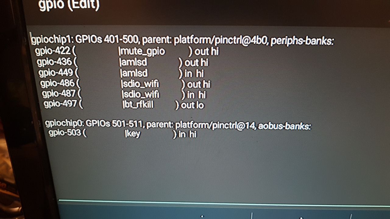
[ 21.261541@3] OpenVFD: Detected gpio chips: ao-bank, banks.
[ 21.261547@3] OpenVFD: “banks” chip found. base = 155, pin count = 101, pin = 65, offset = 220
[ 21.261551@3] OpenVFD: “banks” chip found. base = 155, pin count = 101, pin = 64, offset = 219
[ 21.261555@3] OpenVFD: Skipping vfd_gpio_stb evaluation (0xFF)
[ 21.261558@3] OpenVFD: Skipping vfd_gpio0 evaluation (0xFF)
[ 21.261562@3] OpenVFD: Skipping vfd_gpio1 evaluation (0xFF)
[ 21.261565@3] OpenVFD: Skipping vfd_gpio2 evaluation (0xFF)
[ 21.261567@3] OpenVFD: Skipping vfd_gpio3 evaluation (0xFF)
[ 21.266081@3] OpenVFD: Select FD650 controller
[ 21.266167@3] OpenVFD: SW I2C interface intialized (address = 0x0000 (N/A), MSB mode, pull-ups off)
[ 28.852961@3] OpenVFD: Select FD650 controller
can anyone help me to make it work?
Thanks.
device starts with ki plus dtb
Sadly, there’s no info on what type of vfd driver, nor how it’s connected internally.
Maybe the original Android DTB would help, but I wouldn’t count on it too much.

Ok, try this one:
ki-plus-vfd.conf (1.2 KB)
If it doesn’t work, try to swap the 69/70 values around in vfd_gpio_clk/vfd_gpio_dat
I tried 69/70 and swap them to 70/69, but no luck. The display is off.
dmesg:
CoreELEC:~ # dmesg | grep Open
[ 0.390294@1] ohci_hcd: USB 1.1 ‘Open’ Host Controller (OHCI) Driver
[ 21.269646@2] OpenVFD: Version: V1.3.0
[ 21.269663@2] OpenVFD: vfd_gpio_clk: #0 = 0x00; #1 = 0x46; #2 = 0x00;
[ 21.269668@2] OpenVFD: vfd_gpio_dat: #0 = 0x00; #1 = 0x45; #2 = 0x00;
[ 21.269674@2] OpenVFD: vfd_gpio_stb: #0 = 0x00; #1 = 0x00; #2 = 0xFF;
[ 21.269679@2] OpenVFD: vfd_gpio0: #0 = 0x00; #1 = 0x00; #2 = 0xFF;
[ 21.269684@2] OpenVFD: vfd_gpio1: #0 = 0x00; #1 = 0x00; #2 = 0xFF;
[ 21.269689@2] OpenVFD: vfd_gpio2: #0 = 0x00; #1 = 0x00; #2 = 0xFF;
[ 21.269694@2] OpenVFD: vfd_gpio3: #0 = 0x00; #1 = 0x00; #2 = 0xFF;
[ 21.269698@2] OpenVFD: vfd_gpio_protocol: #0 = 0x00; #1 = 0x00;
[ 21.269705@2] OpenVFD: vfd_chars: #0 = 0x02; #1 = 0x01; #2 = 0x02; #3 = 0x03; #4 = 0x04;
[ 21.269712@2] OpenVFD: vfd_dot_bits: #0 = 0x00; #1 = 0x01; #2 = 0x02; #3 = 0x03; #4 = 0x04; #5 = 0x05; #6 = 0x06;
[ 21.269718@2] OpenVFD: vfd_display_type: #0 = 0x04; #1 = 0x00; #2 = 0x00; #3 = 0x03;
[ 21.269724@2] OpenVFD: Detected gpio chips: ao-bank, banks.
[ 21.269730@2] OpenVFD: “banks” chip found. base = 155, pin count = 101, pin = 70, offset = 225
[ 21.269735@2] OpenVFD: “banks” chip found. base = 155, pin count = 101, pin = 69, offset = 224
[ 21.269738@2] OpenVFD: Skipping vfd_gpio_stb evaluation (0xFF)
[ 21.269741@2] OpenVFD: Skipping vfd_gpio0 evaluation (0xFF)
[ 21.269744@2] OpenVFD: Skipping vfd_gpio1 evaluation (0xFF)
[ 21.269748@2] OpenVFD: Skipping vfd_gpio2 evaluation (0xFF)
[ 21.269750@2] OpenVFD: Skipping vfd_gpio3 evaluation (0xFF)
[ 21.272268@2] OpenVFD: Select FD650 controller
[ 21.272347@2] OpenVFD: SW I2C interface intialized (address = 0x0000 (N/A), MSB mode, pull-ups off)
[ 28.508009@2] OpenVFD: Select FD650 controller
The DTB file you attached doesn’t seem to be an actual DTB file but something else.
I can’t decompile it.
I performed the command: dd if=/dev/dtb | gzip > /storage/downloads/dtb.img.gz
from CE
Maybe it is the DTB, but the first part of it is corrupted or missing.
Can you try to run this command from android? I’m not sure that would work, though.
Edit: I went over another VFD part I found in the DTB, and the pin numbers seem to be correct. Another possible issue is that the controller may not be FD650.
I did the dd command over adb, and the dump files are the same. If you want, I can upload it.
Can you open the device and see what the VFD controller chip is?
Or you can give the following config a try:
vfd_display_type='0x05,0x00,0x00,0x04'
very strange:
CoreELEC:~ # dmesg | grep Open
[ 0.389590@1] ohci_hcd: USB 1.1 ‘Open’ Host Controller (OHCI) Driver
[ 21.225307@1] OpenVFD: Version: V1.3.0
[ 21.225325@1] OpenVFD: vfd_gpio_clk: #0 = 0x00; #1 = 0x46; #2 = 0x00;
[ 21.225331@1] OpenVFD: vfd_gpio_dat: #0 = 0x00; #1 = 0x45; #2 = 0x00;
[ 21.225336@1] OpenVFD: vfd_gpio_stb: #0 = 0x00; #1 = 0x00; #2 = 0xFF;
[ 21.225341@1] OpenVFD: vfd_gpio0: #0 = 0x00; #1 = 0x00; #2 = 0xFF;
[ 21.225347@1] OpenVFD: vfd_gpio1: #0 = 0x00; #1 = 0x00; #2 = 0xFF;
[ 21.225352@1] OpenVFD: vfd_gpio2: #0 = 0x00; #1 = 0x00; #2 = 0xFF;
[ 21.225357@1] OpenVFD: vfd_gpio3: #0 = 0x00; #1 = 0x00; #2 = 0xFF;
[ 21.225362@1] OpenVFD: vfd_gpio_protocol: #0 = 0x00; #1 = 0x00;
[ 21.225368@1] OpenVFD: vfd_chars: #0 = 0x02; #1 = 0x01; #2 = 0x02; #3 = 0x03; #4 = 0x04;
[ 21.225375@1] OpenVFD: vfd_dot_bits: #0 = 0x00; #1 = 0x01; #2 = 0x02; #3 = 0x03; #4 = 0x04; #5 = 0x05; #6 = 0x06;
[ 21.225381@1] OpenVFD: vfd_display_type: #0 = 0x05; #1 = 0x00; #2 = 0x00; #3 = 0x04;
[ 21.225388@1] OpenVFD: Detected gpio chips: ao-bank, banks.
[ 21.225394@1] OpenVFD: “banks” chip found. base = 155, pin count = 101, pin = 70, offset = 225
[ 21.225398@1] OpenVFD: “banks” chip found. base = 155, pin count = 101, pin = 69, offset = 224
[ 21.225402@1] OpenVFD: Skipping vfd_gpio_stb evaluation (0xFF)
[ 21.225405@1] OpenVFD: Skipping vfd_gpio0 evaluation (0xFF)
[ 21.225408@1] OpenVFD: Skipping vfd_gpio1 evaluation (0xFF)
[ 21.225411@1] OpenVFD: Skipping vfd_gpio2 evaluation (0xFF)
[ 21.225414@1] OpenVFD: Skipping vfd_gpio3 evaluation (0xFF)
[ 21.227469@1] OpenVFD: Select HBS658 controller
[ 21.227547@1] OpenVFD: SW I2C interface intialized (address = 0x0000 (N/A), LSB mode, pull-ups off)
[ 29.320736@0] OpenVFD: Select FD650 controller
[ 29.320971@0] OpenVFD: SW I2C interface intialized (address = 0x0000 (N/A), MSB mode, pull-ups off)
The display still off. I will open the box.
it’s probably something with the openvfd addon. Make sure to turn off the advanced tab.
But you’d really need to open the box up to see which controller it’s using.
@TheCoolest, @swimm3r told me fd6551 is the chip of display. he cant post anymore.
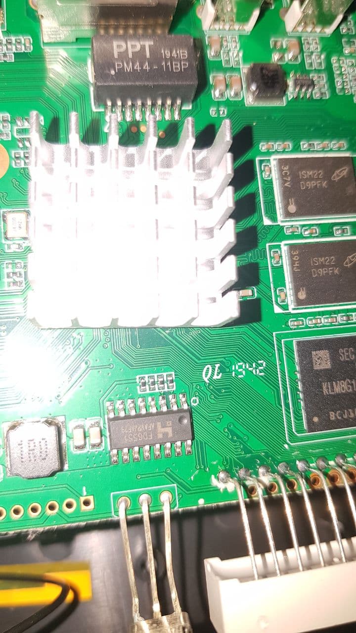
In that case, it should be
vfd_display_type='0x05,0x00,0x00,0x06'
The first value (0x05) of the display type may need to be adjusted.
I would recommend to disable/remove the OpenVFD Service addon during testing.
And try swapping the 69\70 value again, if needed.
perfect. it is working.
vfd_gpio_clk=‘0,69,0’
vfd_gpio_dat=‘0,70,0’
vfd_gpio_stb=‘0,0,0xFF’
vfd_display_type=‘0x05,0x00,0x00,0x06’
Colon not work
the remained thing is vfd_chars.
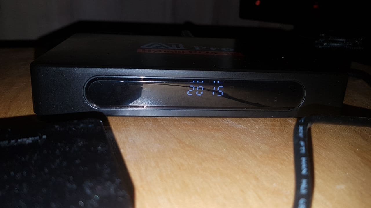
vfd_chars=‘0,4,3,2,1’ its ok
and now all work. Thanks @The Coolest you are the best.
You can to push the file to vfd repo.
Thanks
A1-pro-vfd.conf (1.2 KB)
Great, thanks.
@TheCoolest Thank you very much for your support.
Yesterday I was not allowed to post anymore.