Do you have any plans to look at that? I guess it will be possible if there’s some way to get channel number, then it should not be any problem to show value on lcd
To be honest, I don’t really have time for this right now.
The source is on GitHub, so anyone is welcome to take a look.
Ok, so that can be considered as one of todo things
I just installed this for T95 Max Plus S905X3 CE 9.2.5 ng and this work very good but I can say my remote is less responsive after I activated this … ( I use my old S912 remote for CE…)
EDIT: I disabled the VFD service and my remote come back reactive and work good now, I only see the hour and nothing about network or some but its ok
@TheCoolest quick question about the addon, how easy/impossible is it to add support for updating the VFD from outside of CoreELEC, say via json-rpc commands to Kodi?
not making a request, just wanting to understand if it’s doable.
(for example for showing the active HDMI source, or a PC playing music or video)
I own Vontar X3 on the same 905X3 board and OpenVDF does not affect how remote works. I think vfd has nothing to do with remote. Make sure you used remote.conf, it works much better.
I use my old remote from S912 box which do not work with this T95 Max Plus Box excepted in CE… and yes my old remote is affected by VFD service I dont know why 75% less reactive when this service is enabled
help me please start the display on the m96x II Plus box …
controller fd628 gpio conclusions with android where the display works I attach
controller fd628 gpio conclusions with android where the display works I attach
See if one of these will work
1-m96x-ii-plus-s905x3-vfd.conf (1.2 KB)
2-m96x-ii-plus-s905x3-vfd.conf (1.2 KB)
The display still does not work with any of these configurations
Have you opened the box and verified that the vfd chip is actually FD628?
FD628 requires 3 control pins, FD65x requires 2. I see only 2 entries for FD628 in your screenshot, so I assumed that the box is actually using a FD65x chip.
It’s also possible that it uses a HBS658 chip, which is different, and requires a different configuration.
Okay, I’ll open the box today
1 Like
I opened the box, and indeed there is another microcircuit there, it is very hard to see, this microcircuit is either fd655s or fd855s, the first digit is very hard to see, I cannot see …
I recently bought a TX3 mini that appears to have different hardware than those reported to be fully supported by CE. It boots CE fine, but wifi/bt and the vfd are not working.
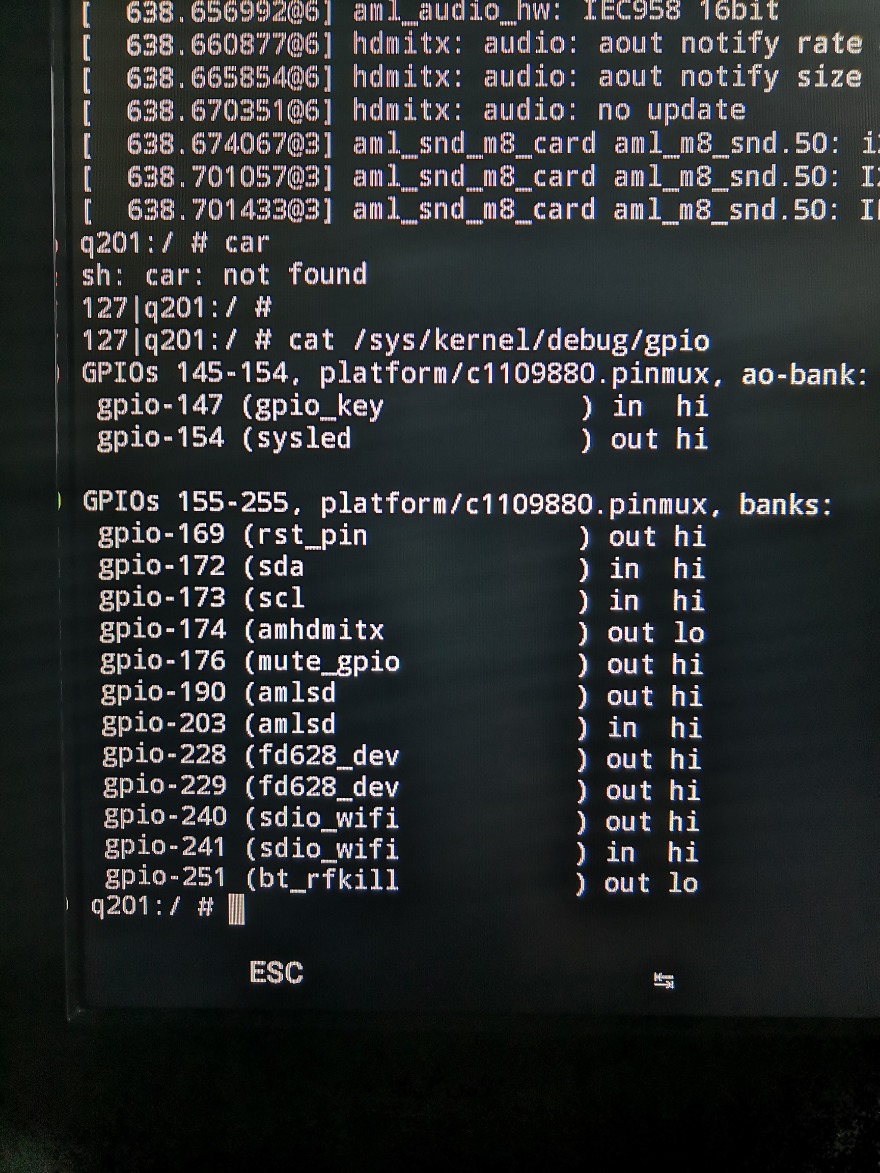
I opened up the box and noticed it has a FD650B-S VFD chip. Moreover, issuing cat /sys/kernel/debug/gpio in Android gives:
GPIOs 145-154, platform/c1109880.pinmux, ao-bank:
gpio-147 (gpio_key ) in hi
GPIOs 155-255, platform/c1109880.pinmux, banks:
gpio-172 (sda ) in hi
gpio-173 (scl ) in hi
gpio-176 (mute_gpio ) out hi
gpio-190 (amlsd ) out hi
gpio-203 (amlsd ) in hi
gpio-228 (sysled ) out hi
gpio-230 (fd650_dat ) in hi
gpio-231 (fd650_clk ) out hi
gpio-240 (sdio_wifi ) out hi
gpio-241 (sdio_wifi ) in hi
gpio-251 (bt_rfkill ) in lo
Anyone who can tell me how to create a working vfd.conf from this information?
vfd_gpio_clk 0.76.0
vfd_gpio_dat 0.75.0
vfd_gpio_stb 0.0.0xFF
Try this config тх3 mini
Thanks. I used the vfd.conf for the TX3 mini and changed the 3 parameters as per your request. It’s not working, but I do see kernel VFD messages:
[ 11.414062@2] OpenVFD: Version: V1.3.0
[ 11.414080@2] OpenVFD: vfd_gpio_clk: #0 = 0x00; #1 = 0x4C; #2 = 0x00;
[ 11.414084@2] OpenVFD: vfd_gpio_dat: #0 = 0x00; #1 = 0x4B; #2 = 0x00;
[ 11.414089@2] OpenVFD: vfd_gpio_stb: #0 = 0x00; #1 = 0x00; #2 = 0xFF;
[ 11.414093@2] OpenVFD: vfd_gpio0: #0 = 0x00; #1 = 0x00; #2 = 0xFF;
[ 11.414098@2] OpenVFD: vfd_gpio1: #0 = 0x00; #1 = 0x00; #2 = 0xFF;
[ 11.414102@2] OpenVFD: vfd_gpio2: #0 = 0x00; #1 = 0x00; #2 = 0xFF;
[ 11.414106@2] OpenVFD: vfd_gpio3: #0 = 0x00; #1 = 0x00; #2 = 0xFF;
[ 11.414110@2] OpenVFD: vfd_gpio_protocol: #0 = 0x00; #1 = 0x00;
[ 11.414116@2] OpenVFD: vfd_chars: #0 = 0x04; #1 = 0x03; #2 = 0x02; #3 = 0x01; #4 = 0x00;
[ 11.414123@2] OpenVFD: vfd_dot_bits: #0 = 0x00; #1 = 0x01; #2 = 0x02; #3 = 0x03; #4 = 0x04; #5 = 0x05; #6 = 0x06;
[ 11.414128@2] OpenVFD: vfd_display_type: #0 = 0x01; #1 = 0x00; #2 = 0x00; #3 = 0x00;
[ 11.414137@2] OpenVFD: Detected gpio chips: periphs-banks, aobus-banks.
[ 11.414145@2] OpenVFD: “periphs-banks” chip found. base = 401, pin count = 100, pin = 76, offset = 477
[ 11.414149@2] OpenVFD: “periphs-banks” chip found. base = 401, pin count = 100, pin = 75, offset = 476
[ 11.414152@2] OpenVFD: Skipping vfd_gpio_stb evaluation (0xFF)
[ 11.414154@2] OpenVFD: Skipping vfd_gpio0 evaluation (0xFF)
[ 11.414155@2] OpenVFD: Skipping vfd_gpio1 evaluation (0xFF)
[ 11.414157@2] OpenVFD: Skipping vfd_gpio2 evaluation (0xFF)
[ 11.414159@2] OpenVFD: Skipping vfd_gpio3 evaluation (0xFF)
[ 11.415134@1] OpenVFD: Select FD628 controller
[ 11.415174@1] OpenVFD: SW SPI 3-wire interface failed to intialize. Invalid CLK (477), DAT (476) or STB (-2) pins
[ 11.415178@1] OpenVFD: Failed to initialize the controller, reverting to Dummy controller
Then it’s most likely a FD655S, should be similar/identical in functionality to the FD655.
Try to change
vfd_display_type='0x01,0x00,0x00,0x06' to vfd_display_type='0x01,0x00,0x00,0x05' in both files and give them a try.
Also, if it still doesn’t work, reboot and then post a dmesg log, perhaps there is a conflict with the pins with another driver.
You can run dmesg | paste in ssh and paste the link here.
@machello
Try this file
tanix-tx3-2-vfd.conf (1.2 KB)
Please let me know if it works or not.
Great…looks like we’re slowly getting there: I’m getting results. I tried several configurations, bu since the chip inside the box is labelled FD650B-S the file that you supplied (with vfd_display_type=‘0x01,0x00,0x00,0x03’) seems most promising.
The display now shows this:

And dmesg |grep -i vfd gives this:
[ 11.506018@2] OpenVFD: Version: V1.3.0
[ 11.506031@2] OpenVFD: vfd_gpio_clk: #0 = 0x00; #1 = 0x4C; #2 = 0x00;
[ 11.506035@2] OpenVFD: vfd_gpio_dat: #0 = 0x00; #1 = 0x4B; #2 = 0x00;
[ 11.506039@2] OpenVFD: vfd_gpio_stb: #0 = 0x00; #1 = 0x00; #2 = 0xFF;
[ 11.506044@2] OpenVFD: vfd_gpio0: #0 = 0x00; #1 = 0x00; #2 = 0xFF;
[ 11.506048@2] OpenVFD: vfd_gpio1: #0 = 0x00; #1 = 0x00; #2 = 0xFF;
[ 11.506052@2] OpenVFD: vfd_gpio2: #0 = 0x00; #1 = 0x00; #2 = 0xFF;
[ 11.506056@2] OpenVFD: vfd_gpio3: #0 = 0x00; #1 = 0x00; #2 = 0xFF;
[ 11.506060@2] OpenVFD: vfd_gpio_protocol: #0 = 0x00; #1 = 0x00;
[ 11.506066@2] OpenVFD: vfd_chars: #0 = 0x04; #1 = 0x03; #2 = 0x02; #3 = 0x01; #4 = 0x00;
[ 11.506073@2] OpenVFD: vfd_dot_bits: #0 = 0x00; #1 = 0x01; #2 = 0x02; #3 = 0x03; #4 = 0x04; #5 = 0x05; #6 = 0x06;
[ 11.506077@2] OpenVFD: vfd_display_type: #0 = 0x01; #1 = 0x00; #2 = 0x00; #3 = 0x03;
[ 11.506083@2] OpenVFD: Detected gpio chips: periphs-banks, aobus-banks.
[ 11.506090@2] OpenVFD: “periphs-banks” chip found. base = 401, pin count = 100, pin = 76, offset = 477
[ 11.506093@2] OpenVFD: “periphs-banks” chip found. base = 401, pin count = 100, pin = 75, offset = 476
[ 11.506096@2] OpenVFD: Skipping vfd_gpio_stb evaluation (0xFF)
[ 11.506097@2] OpenVFD: Skipping vfd_gpio0 evaluation (0xFF)
[ 11.506099@2] OpenVFD: Skipping vfd_gpio1 evaluation (0xFF)
[ 11.506101@2] OpenVFD: Skipping vfd_gpio2 evaluation (0xFF)
[ 11.506103@2] OpenVFD: Skipping vfd_gpio3 evaluation (0xFF)
[ 11.507091@1] OpenVFD: Select FD650 controller
[ 11.507181@1] OpenVFD: SW I2C interface intialized (address = 0x0000 (N/A), MSB mode, pull-ups off)
How should I proceed from here?
Change the vfd_chars settings to this: vfd_chars='2,0,1,2,3'
And vfd_display_type to vfd_display_type=‘0x00,0x00,0x00,0x03’
Great! I’m getting readable characters now and they’re no longer upside down. Now, there’s only one thing left: how to get it to display the correct time? It currently says:
0:41
CoreELEC:~ # date
Wed Mar 10 10:41:43 CET 2021
Not sure if that means the time is just off, or that it’s lacking the first character?