How to configure VFD

Hello -

I have a Tannix TX3 mini+, S905W2. I’ve tried the TX3 mini VFD and I just get the “four eights” display which indicates it’s not working. I’ve attached the gpio output from the box when booted to android with a working clock display. Can I get a config for this device or a good how-to on how to make one?

Thanks!


Try the tanix-w2 vfd.
If it doesn’t work, try swapping the values of vfd_gpio_clk and vfd_gpio_dat and try again.

Tanix-w2 was the ticket, thanks! There were only a couple in the tanix family I had not tried and that was one of them.

Is there any means/plan to add 12-hr clock support for these?

Great!
No firm plans right now, but it may come.
One of the main issues I see with 12H on these displays is that you can’t really display AM/PM on them.

Understood. Personally, I’ve never confused 1 AM with 1 PM for obvious reasons, so I don’t consider that to be a concern. Military time is the most accurate display, but a 12-hour clock is a personal preference. Ideally, it would be a setting in the Coreelec VFD plugin so the user could decide what they prefer.

Thanks again for the assistance!

Hi, I have a x96 mini plus box and have tried a good few of the vfd configurations and am not really having much luck… could anyone help on which should be used?

I have included my dmesg.

https://paste.coreelec.org/L5VvyR

And if this does have the information, which line would indicate the controller used and which vfd to use?

Thanks a million for any help!

Run cat /sys/kernel/debug/gpio on Android and post the output from it.

21.665050

Open VFD Select FD628

You still will need info from Android

What the Coolest request

Sorry for my late reply…

cat /sys/kernel/debug/gpio
gpiochip1: GPIOs 401-500, parent: platform/pinctrl@4b0, periphs-banks:
gpio-422 ( |mute_gpio ) out hi
gpio-436 ( |amlsd ) out hi
gpio-449 ( |amlsd ) in hi
gpio-486 ( |sdio_wifi ) out hi
gpio-487 ( |sdio_wifi ) in hi
gpio-497 ( |bt_rfkill ) in lo

gpiochip0: GPIOs 501-511, parent: platform/pinctrl@14, aobus-banks:
gpio-503 ( |key ) in hi
gpio-504 ( |stb_gpio ) out lo
gpio-505 ( |clock_gpio ) out hi
gpio-506 ( |data_gpio ) out hi

I opened the box and it has a tm1628a controller… tried the configs mentioned in this thread for that controller, but unfortunately none of them have made anything display on the lcd at all.

Took a picture of the lcd if that help identify it…

WhatsApp Image 2024-03-21 at 10.15.27 AM

Try this one:
x96-mini-plus-s905w2.conf (1.2 KB)

Thanks a million… that vfd got the lcd to display on reboot, however the text is jumbled…

Try this
x96-mini-plus-s905w2.conf (1.2 KB)

thanks… however that config was still jumbled.

Looking at your config, i set the common anode on your original config and the clock worked perfectly…

vfd_display_type=‘0x05,0x00,0x01,0x02’

the dots are not mapped correctly, setup is mapped to usb and ethernet is mapped to hdmi.

when i run:
/usr/sbin/OpenVFDService -t -dt 0x02010005 &

the dots cycle in order: apps, setup, usb, card, colon, hdmi, cvbs…

I noticed that the lcd display does not match the silk screened icons on it!!! (with ethernet and wifi icons missing). So it is responding like display type 5, but with the dot icons of display 2!

Try to change the dots:
vfd_dot_bits=‘0,2,1,3,4,5,6’
or
vfd_dot_bits=‘0,1,2,3,4,5,6’

thanks so much for all your help…

That is not mapping the events correct though?

Ethernet connectivity is driving hdmi icon, where there is no ethernet dot available…

It appears to be a display type 5, but with the dot icons from a type 2 if that makes sense?

(apps, setup, usb, card, hdmi and cvbs available dots, but events not tied correctly to them?)

Ah sorry, you’re right.
You must use type 2, otherwise it uses the layout of the “naked” display, which is different.
Doesn’t the clock work with display type 2?

Hi thanks for your reply,

No, not 100% working as display 2… some of the segments are missing… included screen of ce21 on boot and current time of 0722… the colon and dots appear to be working fine in display 2 however…

I’m a little confused. If you use display type 5, then the clock shows up correctly, but display type 2 does shows like the pic you posted?
What about the icons when type 2 is used?

hi… yep, that is correct… when i use display 5 the clock and colon works fine, but icons are incorrect combination, so can’t be correct… when i use display 2 it shows as the pictures, however the icons are functional… just thinking, in my case, the icons don’t really offer me too much additional information compared to the other set of icons, so i am just going to disable the dots and use the clock of display 5…

Hi, i have this cfg - for X96 Max Plus Ultra

image

# This file must be renamed to vfd.conf and placed in the /storage/.config/ folder.
#
# X96 Max Ultea (S905X4) configuration
#--------------------
#gpio_xxx:
# [0] 0 = &gpio, 1 = &gpio_ao.
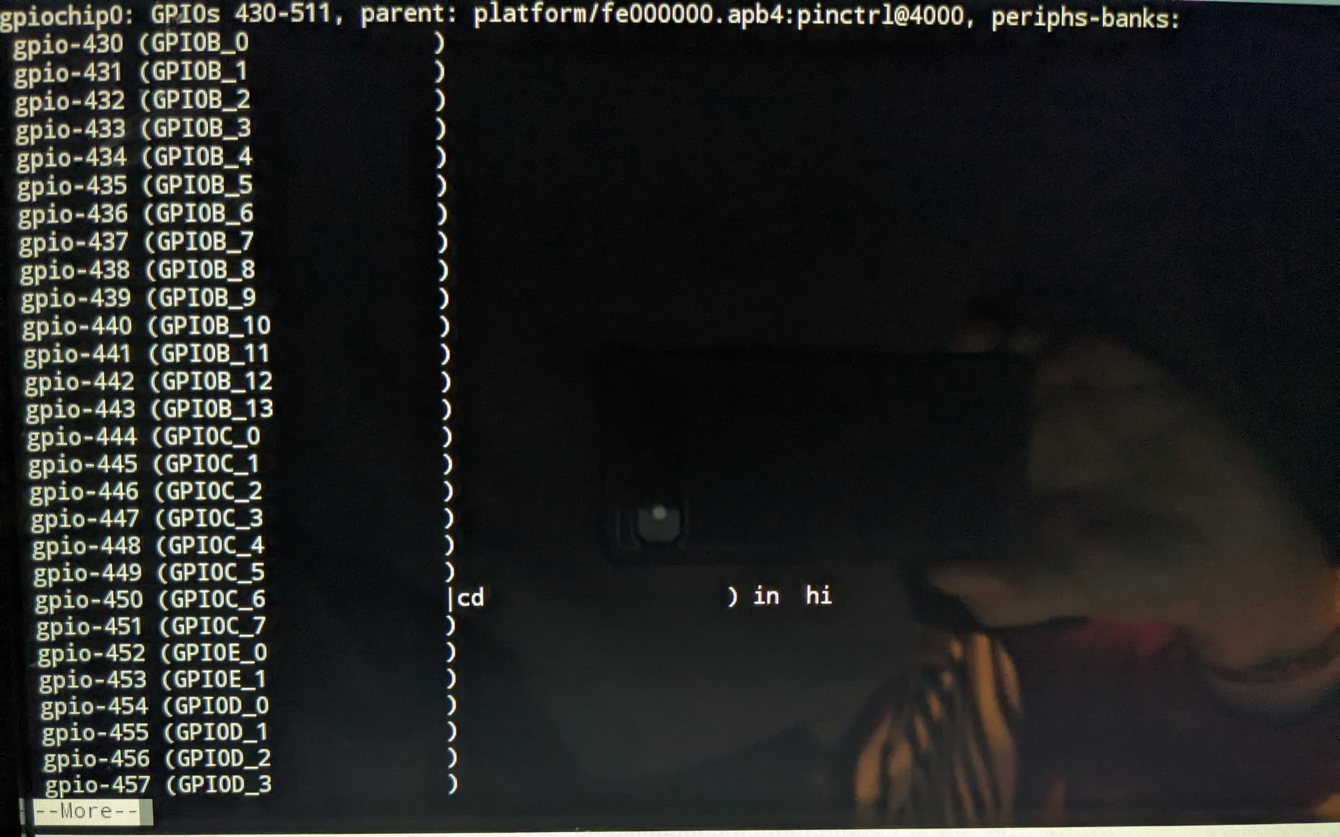
# [1] pin number - https://github.com/CoreELEC/linux-amlogic/blob/amlogic-4.9-19/include/dt-bindings/gpio/meson-sc2-gpio.h
# [0] Reserved - must be 0.

vfd_gpio_clk='0,1,0'
vfd_gpio_dat='0,0,0'
vfd_gpio_stb='0,39,0'

#chars:
# < DHHMM > Order of display chars (D=dots, represented by a single char)

vfd_chars='4,0,1,2,3'

#dot_bits:
# Order of dot bits. Typical configurations:
# Display Type 0, 1 usually has Alarm, USB, Play, Pause, Col, Ethernet, Wifi dots
# Alarm = 0, USB = 1, Play = 2, Pause = 3, Col = 4, Eth = 5, Wifi = 6
# Display Type 2 usually has APPS, USB, SETUP, CARD, Col, HDMI, CVBS dots
# APPS = 0, USB = 1, SETUP = 2, CARD = 3, Col = 4, HDMI = 5, CVBS = 6
# Display Type 3 Power, LAN, Col, Low Wifi, High Wifi
# N/A = 0, N/A = 1, Power = 2, LAN = 3, Col = 4, Low Wifi = 5, High Wifi = 6

vfd_dot_bits='0,1,2,3,4,5,6'

#display_type:
# [0] - Display type.
# [1] - Reserved - must be 0..
# [2] - Flags. (bit 0 = '1' - Common Anode display)
# [3] - Controller.

vfd_display_type='0x02,0x00,0x01,0x00'

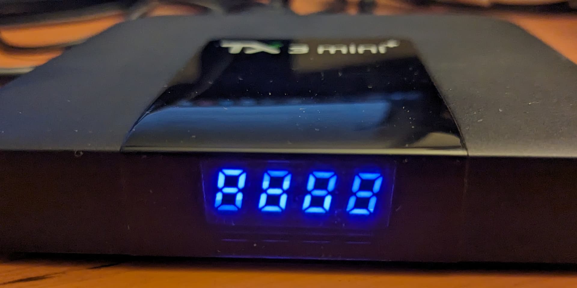
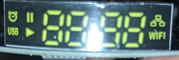
display is OK, but icons not functional in right order (ETH connect)
display have usb, sd, wifi hi, wifi lo, clock, apps, lan

after boot CE from SD light - usb, wifi low, clock :, apps