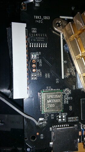
Try with vfd_display_type='0x01,0x00,0x00,0x05'
It is the same. The clock OK, colon not, icons not.
I see you opened the device, can you check what chip it uses? Is it FD650 or FD655 (or FD6551)?
Ok, this looks like a copy of a FD650. The difference between FD650 and FD655 is that a FD650 has support for 4 digits, and 8 segments. The number is made up of 7 segments, so we have 4 more bits for the icons.
Please test
vfd_display_type='0x01,0x00,0x00,0x03'
and
vfd_chars=‘1,4,3,2,1’ or vfd_chars=‘2,4,3,2,1’ or vfd_chars=‘3,4,3,2,1’ or vfd_chars=‘4,4,3,2,1’ and see if any of these options makes the colon work.
Unfortunately, nothing new. I tested yesterday:
#             b 2 1 4 wrong clock and missing colon   b = left top digit blinks
#vfd_chars='4,2,3,1,0'

#             2 0 b 2  wrong clock and missing colon
#vfd_chars='2,4,3,1,0'

#             2 0   2 wrong clock and missing colon
#vfd_chars='3,4,3,1,0'

#             2 b 0 2 wrong clock and missing colon
#vfd_chars='3,4,2,1,0'

#            2 0 3 5 clock OK and missing colon
vfd_chars='0,4,3,2,1'As I said, the first number is the index of the icons digit, the other 4 are the indexes of the number digits.
So it needs to be vfd_chars='x,4,3,2,1' replace x with 1 or 2 or 3 or 4 and see if it makes any of the icons blink, not just the colon.
I understood that. When I replaced only x with 0-4 from your post, nothing blinks. I want to say in my post top that the segment of digit blinks on the top left only when the indexes of the number digits are wrong…
The next step is to run some test patterns and see whether any of the icons light up or not.
You need to ssh into CE, kill the OpenVFDService.
Then run /usr/sbin/OpenVFDService -t and you should see the display start to go through test patterns.
Let me know whether or not the icons start to blink or not.
Ok I understand. Please give me time. I’m away from home now. I’ll be back in about a week. Then I’ll give you information. Thanks
Hello, I am back. I tried it. All icons start to blink.
Ok, before we continue, make sure that you have the OpenVFD Addon installed and that it’s enabled.
If it’s enabled and you still don’t see any icons, then please make a video recording of one full cycle of the test pattern (it’s about 60-70 seconds).
Using the video it may help me figure out why the icons are not working in normal mode.
Which vfd.conf for Magicsee C500 Pro?
I use sm1_s905x3_4g.dtb
cat /sys/kernel/debug/gpio #CE
gpiochip1: GPIOs 410-495, parent: platform/pinctrl@ff634480, periphs-banks:
gpio-448 ( |amlsd ) out hi
gpio-458 ( |amlsd ) in hi
gpio-474 ( |openvfd ) in hi
gpio-475 ( |openvfd ) in lo
gpio-482 ( |sdio_wifi ) out hi
gpio-483 ( |sdio_wifi ) in hi
gpio-493 ( |bt_rfkill ) out hi
gpio-495 ( |bt_rfkill ) out hi
gpiochip0: GPIOs 496-511, parent: platform/pinctrl@ff800014, aobus-banks:
gpio-498 ( |avout_mute ) out hi
gpio-499 ( |key ) in hi
gpio-507 ( |? ) out hi
cat /sys/kernel/debug/gpio #Android
gpiochip1: GPIOs 410-495, parent: platform/pinctrl@ff634480, periphs-banks:
gpio-448 ( |amlsd ) out hi
gpio-458 ( |amlsd ) in hi
gpio-482 ( |sdio_wifi ) out hi
gpio-483 ( |sdio_wifi ) in hi
gpio-493 ( |bt_rfkill ) out hi
gpio-495 ( |bt_rfkill ) out hi
gpiochip0: GPIOs 496-511, parent: platform/pinctrl@ff800014, aobus-banks:
gpio-498 ( |avout_mute ) out hi
gpio-507 ( |? ) out lo
You need to run this command from Android, not CE.
Sadly the Android output has no vfd pinout.
I can’t really help any further without knowing which pins on the SoC the display is connected to.
Another potential thing we can look at is the Android DTB, pull the DTB out of Android and post it.
You can try the Magicsee N5 or N5 Max and see if it works, if not then there’s not much to do.
Magicsee N5 and N5 Max not works. It’s write about S905X2 in vfd.conf file.
I don’t know how get DTB from Android.
Try this:
Try this vfd conf.
magicsee-c500-pro-vfd.conf (1.5 KB)
It’s work very good for me.
Thank You very much.
Are all the icons correct?
