I did this way
1 Like
@startv Thanks
just installed 0.1.3 can’t run
2019-05-19 05:43:08.870 T:3461346160 ERROR: EXCEPTION Thrown (PythonToCppException) : -->Python callback/script returned the following error<–
- NOTE: IGNORING THIS CAN LEAD TO MEMORY LEAKS!
Error Type: <type ‘exceptions.ImportError’>
Error Contents: No module named lib.logging
Traceback (most recent call last):
File “/storage/.kodi/addons/service.odroidn2.oled/service.py”, line 4, in
from lib.logging import *
ImportError: No module named lib.logging
–>End of Python script error report<–
I updated from 0.1.1 to 0.1.3, and it works fine. No errors and all options work OK…
@startv Please re-download 0.1.3 there was a missing file.
It’s working now
Thanks for your great addon/script … I’m running it now on 3 N2s and I like it a lot (couldn’t get regular openvfd service running)!!
I tryed ss1309 128x64. I have some dmesg error
[ 168.017702@0] i2c i2c-2: token 1, master_no(2) 300K addr 0x3c
[ 168.017784@0] i2c i2c-2: [aml_i2c_xfer] error ret = -5 (-EIO)
[ 168.017813@0] i2c i2c-2: token 1, master_no(2) 300K addr 0x3c
[ 168.017896@0] i2c i2c-2: [aml_i2c_xfer] error ret = -5 (-EIO)
[ 168.017925@0] i2c i2c-2: token 1, master_no(2) 300
I dont any modification r3 r4
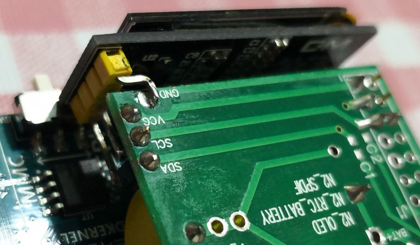
Convenience.
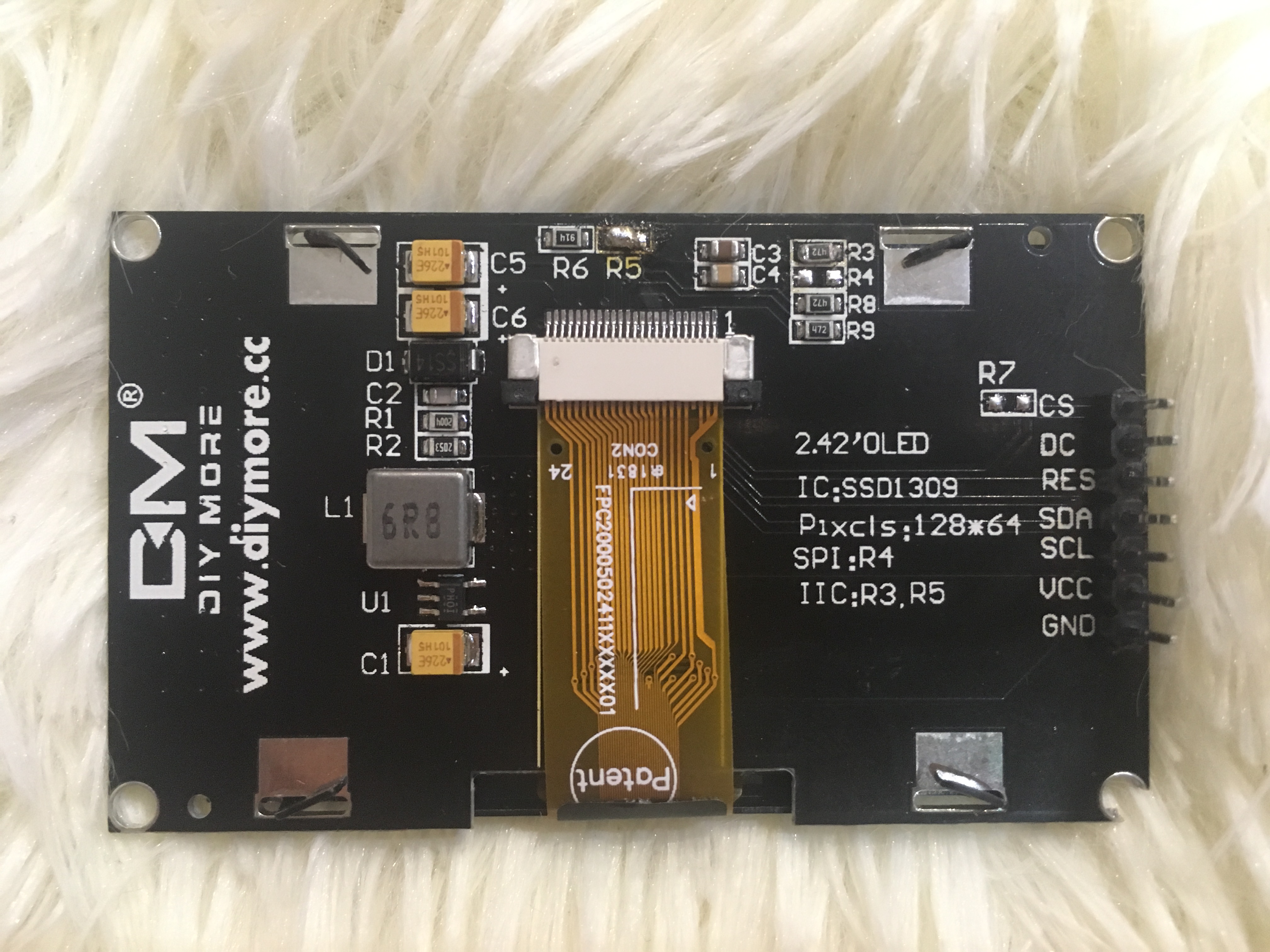
Interface Selection: to choose SPI or IIC interface through R3, R4, R5
For IIC communication, it is necessary to move the resistor on R4 to R3, and R5 is soldered with 0 ohm resistor.
SPI communication or I2C communication can be switched by configuring three resistors R3 R4 R5
too big screens. It look perfect 3-4m
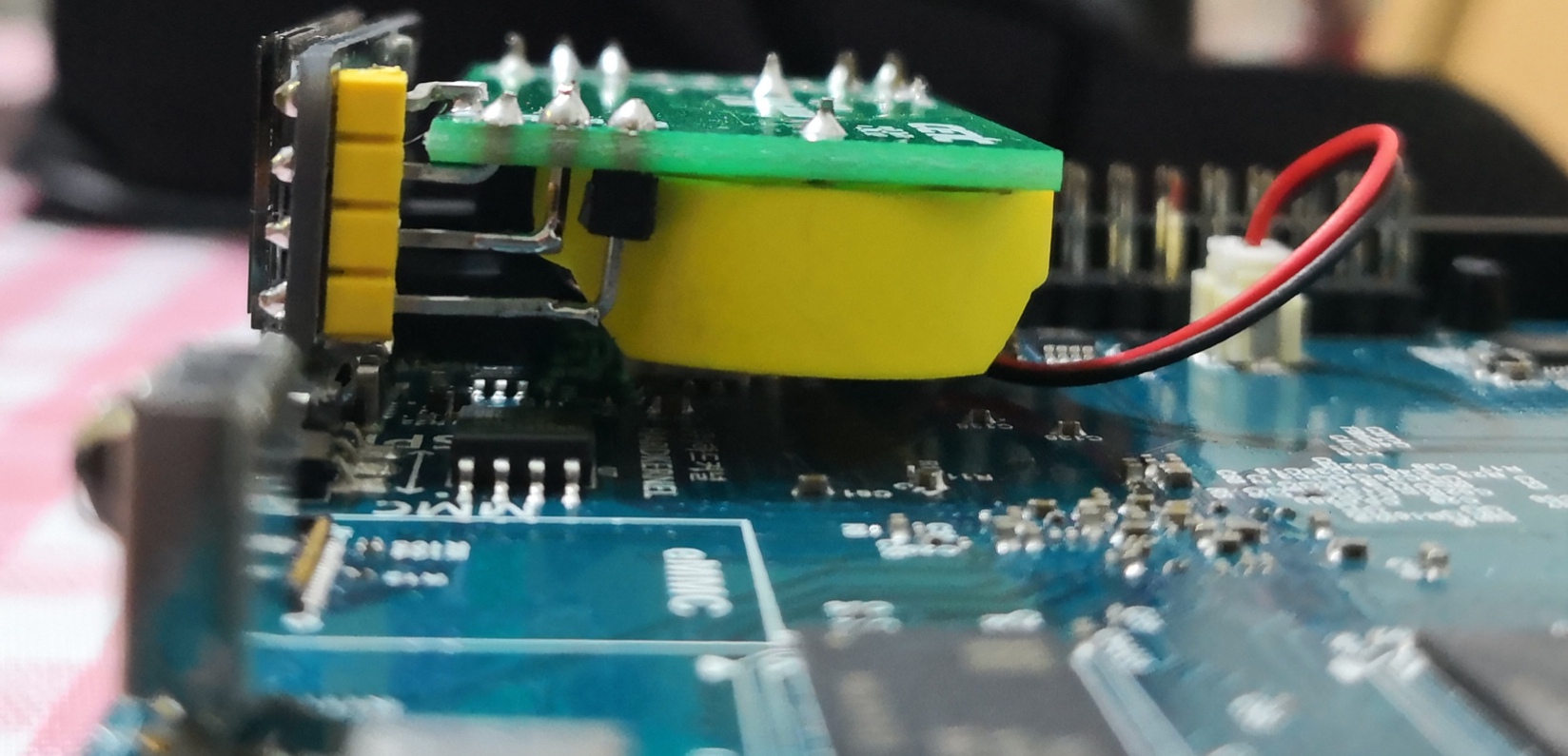
You should check the pcb which shortcuts are soldered (R3, R4, R5).
some russsian buyer write that
“The display is beautiful, delivered quickly, very good seller! The photo shows a little improvements needed to work on the i2c bus. In brief: Dc pin connect to gnd pin Rst pin through 1-10kohm resistor connect to vcc Between the gnd pin and the vcc pin install capacitor 0.1-0.22 uf”
Thus I’m confused
Other user wrote that
I’m delighted! Very good display! Redone under the work of i2c, see the photo that you need to solder, the main thing is to make the reset circuit-reset pull up to power through the resistor 4.7 k and add to gnd capacitor 0,1 uf. Short, r4 rearrange to r3, r5 short, dc pin connect to gnd.
Why are you confused? It tells the same as I see…
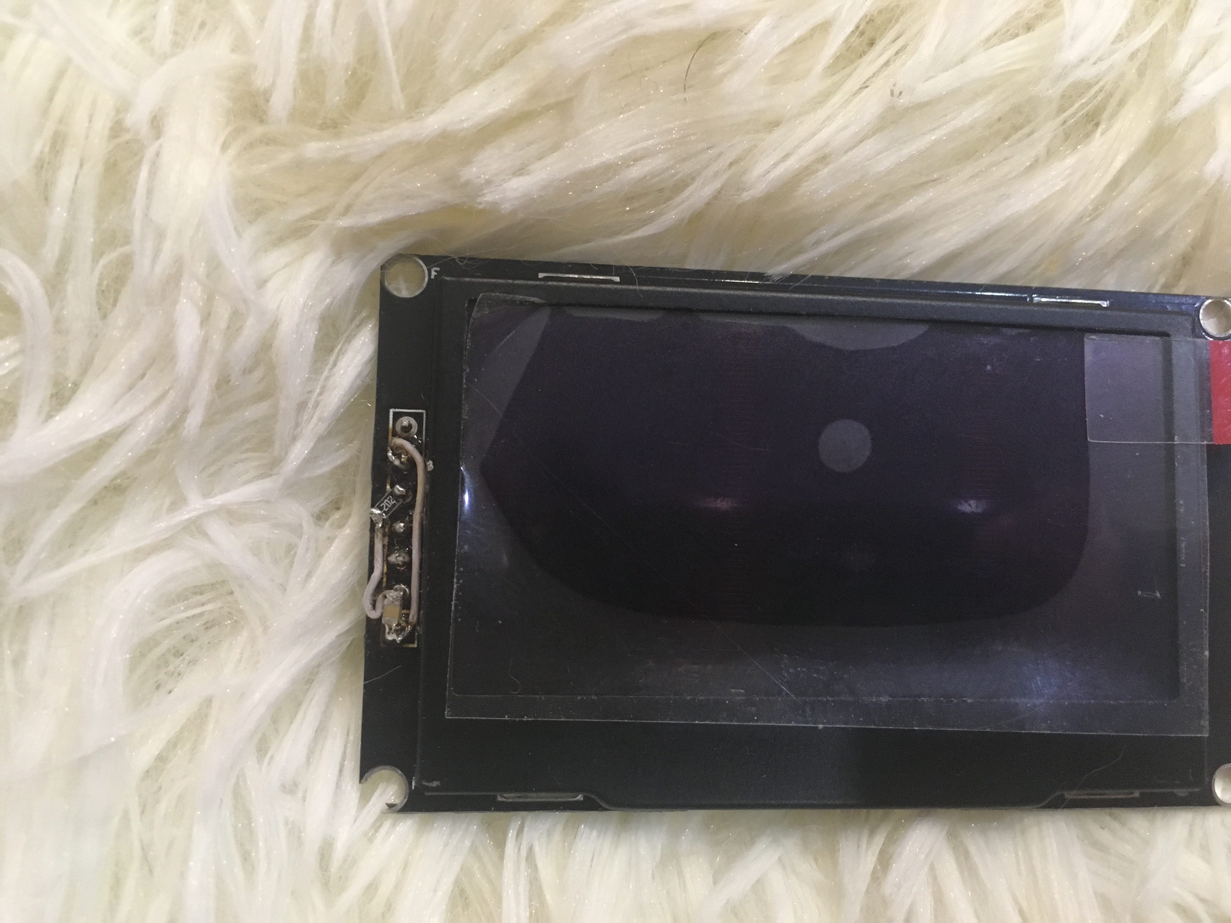
indeed I know to remove r4 resistance to resolder r3.
R4 solder 0 ohm resistance or short. But dont work display. Need modification reset pin and dc pin. Idont find smd 0.1-0.22 uf capacitor
"Dc pin connect to gnd pin Rst pin through 1-10kohm resistor connect to vcc Between the gnd pin and the vcc pin install capacitor 0.1-0.22 uf”
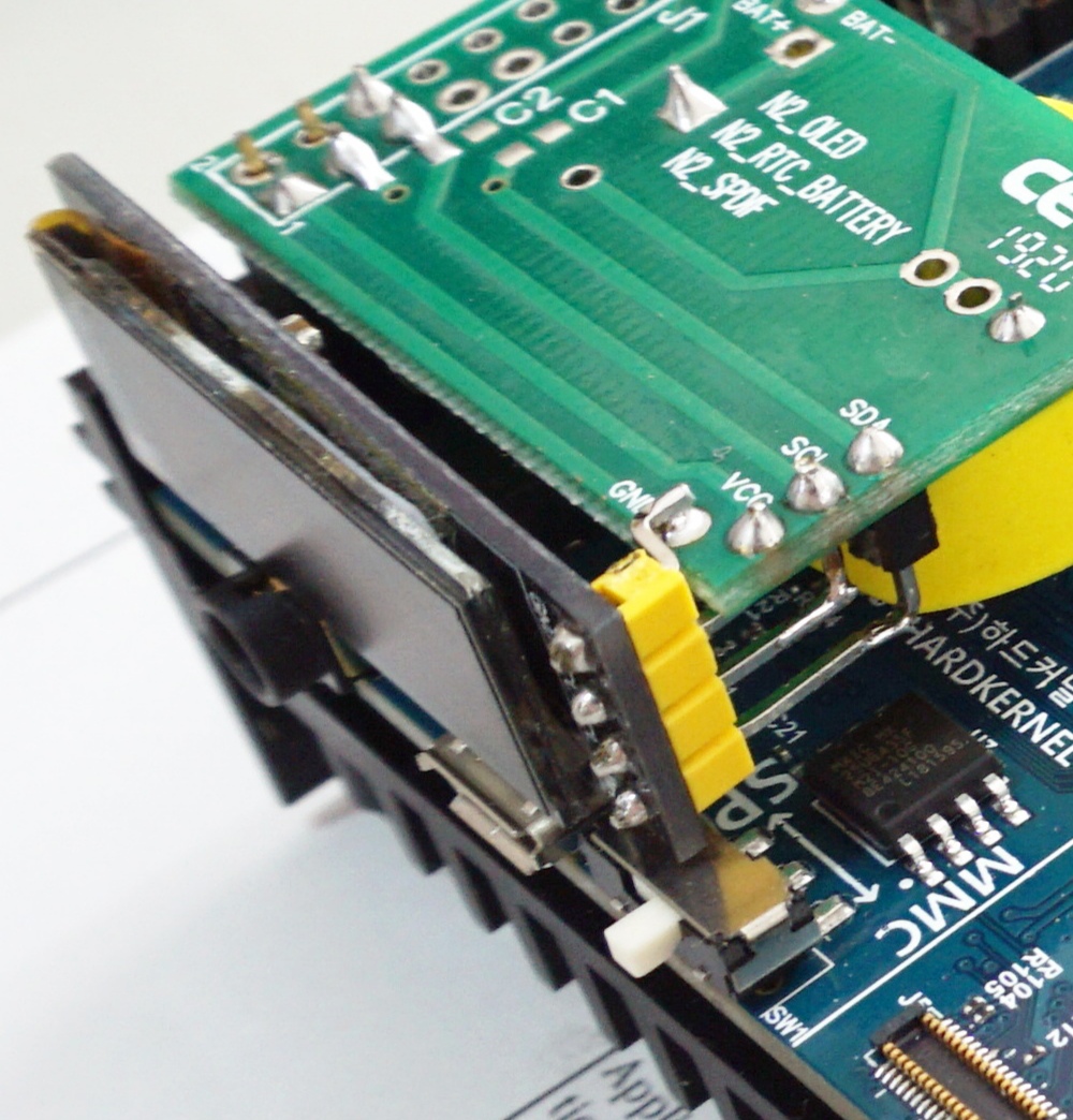
The important things are:
- pull up the reset to vcc (with or without resistor)
- pull down d/c to gnd
- short R3, R5
- remove R4
Also you can connect the reset pin to your sbc’s gpio pin so you can control the io pin to reset the display.
Vcc don’t need extra capacitor as the pcb already has it (I think it is C1)
0.1uF=100nF, 0.22uF=220nF if it is more familiar in this way.
But usually 1uF is the recommended capacitor value between the digital power supply and the ground.
You can open the SSD1309 datasheet, and look at how to configure the controller for I2C operation.
You may also need pullups for the SDA and SCL lines.
The controller can have an address of 0x3C or 0x3D, depending on configuration.
Big thanks I will try
Are these available to purchase?
Matt
no, I just download these PCB file sent to my friend and make some pieces. actually I have 360 pieces.
360?! Lol
Would you sell a couple to me?
Matt
Yes. I’m very like to sent you some pieces for free, but I am not in Europe.
Oh, fair enough.
Thank you.
Matt