SDIO Debug Boards current stock: 0
Back in stock (approximately): unknown
Current price (including postage and packing by standard mail): €15.00
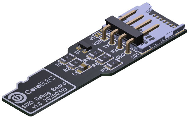
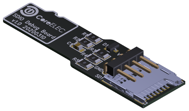
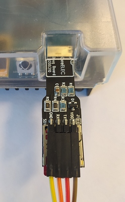
Researched and developed by Team CoreELEC by @anon88919003, @Portisch and @vpeter, we proudly present the universal Amlogic SDIO debug board, the SDIO debug board will give you easy access to the UART interface without needing to open your device and/or without having to modify anything.
Purpose of the SDIO debug board
With dmesg you are limited to retrieving debug logs from the Linux kernel only, if you need logs from bootloader (u-boot) for example if you have a bricked device or a wake up issue from power off/suspend then this adaptor can be easily used to identify issues.
How to use
-
Power of your device and insert the SDIO debug board like a standard micro SD card into the devices memory card slot.
-
If you want to boot from a micro SD card then first insert your currently used micro SD into the SDIO debug board memory card slot and then the SDIO debug board into your devices memory card slot. NOTE: Please keep in mind that the micro SD memory card will use only 1 bit bus mode so reading and writing from the storage will be 4x slower than normal. Currently there looks to be a “bug” located in the kernel and booting devices with the G12A SoC (S905X2) are unable to boot CoreELEC from micro SD when using this SDIO debug board. If this is the case on your device then please boot from eMMC and/or a USB memory device.
-
The 4 pin header is a TTL UART interface, you can use any standard TTL/USB UART adaptor to connect the adaptor to your host computer. The UART connection used is 8N1, 115200bps: 8 bit, parity none, 1 stop bit, baud rate 115200bps.
-
There is a solder jumper (J1) located next to the
VDDpin of the pin header, this solder jumper is not set by default. If you need +3V3 onVDDpin please inform me whilst ordering or short J1 yourself by a solder blob afterwards, in 99% of the use casesVDDisn’t needed.
Recommended UART/TTL converter:
(type of UART converter with compatibility Top-down)
- CP2102
- PL2303
- FT232
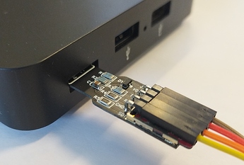
Connection example:
Amlogic devices confirmed working with UART interface by SDIO debug board:
- H96Pro+ (noname, S912)
- Minix NEO T5 (S905X2)
- Minix U22-XJ (S922XJ)
- VIM1 (S905X)
- VIM2 (S912)
- VIM3 (A311D)
- VIM3L (S905D3)
- Odroid N2 (S922X)
- Odroid C4 (S905X3)
- Beelink GS-King (S922XH)
- Beelink GT-King (S922X)
- Beelink GT-King Pro (S922XH)
- Beelink GT1 (S912)
- Beelink GT1mini2 (S905X3)
- M8S (S812)
- Mini M8S II (S905X)
- MXIII (S802)
- UGOOS AM6 (S922X)
- X3 CUBE (S905X3)
- X96 (S905X)
- X96 Max (S905X2)
- XL Home Entertainment Box DV8252 (AX512) (S905X)
- Flix TV Box DV8219 (S905X)
- ZTE B860H V1.1 / V2.1 (S905X)
- ZTE B866 (S905X)
- Fiberhome HG680P (S905X)
Amlogic devices confirmed NOT working SDIO debug board:
- WeTek Play (AML8726-MX)
- Android M8 TV Box (S802)
- GM X92 (S912)
UART terminal Putty
The Amlogic SDIO UART do have issues with fast character transfer. So a delay after each single character sent will be needed. Here is a modified version of Putty 0.74 for Windows which include a delay of 1 millisecond after each single character sent.
How to order:
The SDIO debug board will be sold from and by a private person and not the CoreELEC Team (limited warranty), the board will be delivered fully assembled and tested before hand.
If your device isn’t listed above then there is no guarantee that the SDIO debug board will work as expected. If you have tested the SDIO debug board and your device is not listed above please just post a reply to this thread by [brand/vendor][device type] so we can add it to the list, thank you!
If you want to order an CoreELEC Team SDIO debug board then please contact → @Portisch ← by this link for payment and shipment information!




 But not with this adapter because we didn’t have interest in this area - just uart needed for us.